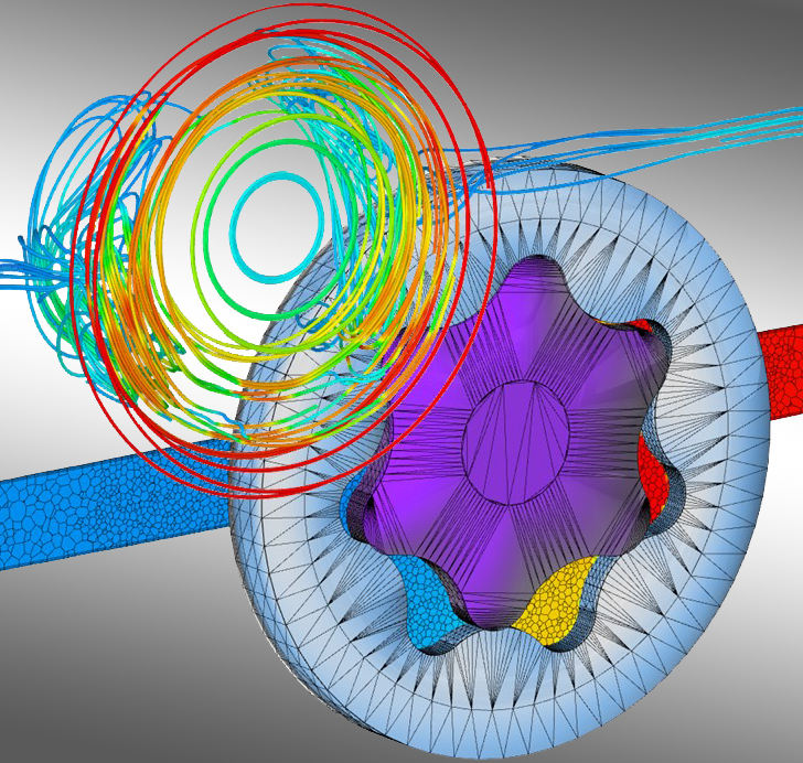
In MRF model a moving reference frame permits an unsteady problem (with respect to the absolute reference frame) to become steady in respect to the moving reference frame. Hence what remains important point is the synergy of information between the stationary frame and the moving reference frame.įor solving turbomachinery problems using CFD there exists specific and special models to be applied, and one of the models being popular in use is the Moving Reference Frame model.

For unsteady (transient) state flow problems the position of the observer hardly matters and is unsteady. Such flows for a stationary observer appears unsteady (around the moving parts) though apparently its a steady state case while when viewed by an observer posted on the rotor appears steady flow. Certainly all the parts attached to the rotating shaft are as well rotating with a certain angular velocity relative to the machine axis, whereas the stationary parts like the stator, casing, inlet(s), exit(s) etc., are devoid of any motion. The MRF approach however requires a special treatment as it has to accord with the modeling and analysis of various existing complex rotating system having components like a stator, rotor in single or multistage. In the current blog we shall try to understand applying MRF model for turbomachinery explained with the help of a simple test case. MRF approach finds application in a wide range of systems like turbomachinery, mixing equipment, electric motors and generators, rotating passages & land and air vehicle motions. There are a number of both generalized and specialized commercial softwares available that apply moving reference frames for both translating and rotating systems. turbomachines) are performed by resorting to moving reference frames (MRF). CFD modeling of flows within systems containing moving components (e.g.

Cdf modeling software#
Having already gone through our blog series of CFD modeling of turbomachinery, wherein we discussed about the CAD Repair and Grid Generation we shall now explore the different solver models available in a commercial software package. To find out if CFD is the right tool for your problem contact us to discuss what we can do for you.CFD Modeling for Turbomachinery using MRF Model Our case studies discuss examples of how we have helped previous clients. These outcomes range from performing modelling to demonstrate how well a facility complies with licensing regulations (or if it doesn’t comply, what the best way to achieve compliance is), through to optimising designs, minimising energy usage, and solving novel problems. Synergetics are experts at CFD modelling, with a proven track record of delivering solid outcomes to our clients.


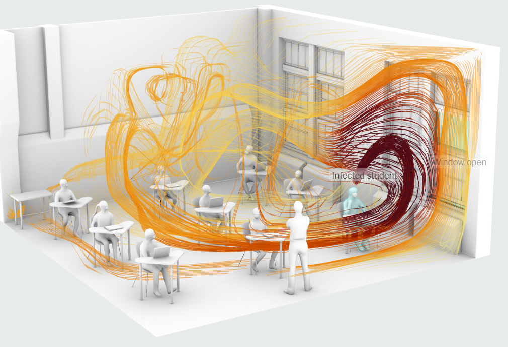
With a wide range of CFD software packages available, CFD has never been more accessible, however if not used correctly it can produce wildly innacurate results. If you have a fluid flow problem, CFD may be able to provide the answer you need. Streamlines and surface contours correspond to the concentration of contaminated air, with red being highly contaminated. Figure 1: CFD modelling of effect of the dispersion of a moist, contaminated, exhaust air gas from cooling towers.


 0 kommentar(er)
